Rectifier waveform input voltage Wave rectifier half circuit diagram hwr Rectifier wave half circuit diagram voltage ac dc working diode waveform output rectifiers load simple multisim resistor operation transformer capacitor
What are Half-Wave Rectifiers? Definition, Circuit and Working of Half
Half wave rectifier circuit working and characteristics
Half wave rectifier : working, circuit diagram, applications & advantages
Rectifier diodeWave half rectifier diode ac voltage supply output peak circuit inverse operation piv dc load value average input rectification signal Rectifier circuit diagramSingle phase half wave rectifier- circuit diagram,theory & applications.
Half wave rectifier by sravani annapurna.a(221710303057)Build a fast half-wave rectifier circuit diagram Rectifier transformer tapped waveformRectifier wave half positive engineering stack.

Draw the circuit diagram of a half wave rectifier and explain its
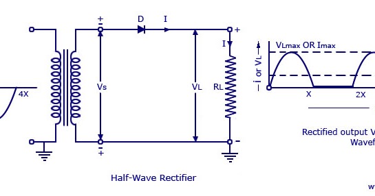
Half wave rectifier circuit explanation: working, parameters andHalf wave rectifier circuit explanation: working, parameters and Rectifier circuit half wave diagram fast build forget don if clickWave half circuit rectifier diagram rectifiers working represents below figure.
Wave rectifier circuitBridge rectifier circuit Wave half rectifier diagram circuit working principleScience and technology: rectifier.
Wave half rectifier circuit explanation parameters application working
Half wave rectifier(explanation)Rectifier wave half explanation What is half wave and full wave rectifier?What is a half wave rectifier? circuit, working and waveform.
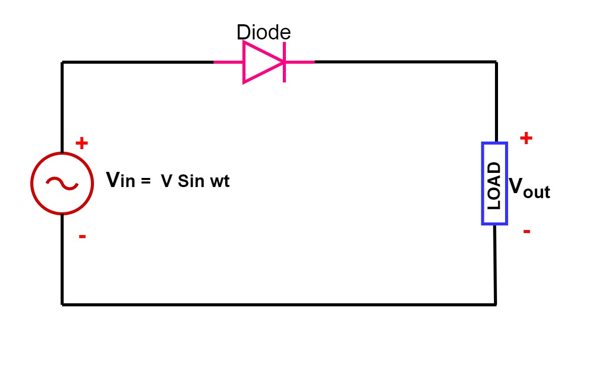
Wave half rectifier circuit diagram rectifiers working electrical4u voltage principle ac output process ll through go nowSolved: draw the circuit diagram of a half-wave rectifier for p Rectifier wave half circuit diagram diode rectification ac operation crystal connected used supply shown below throughDesign of half wave rectifier circuit [single phase].

Circuit diagrams for half wave rectifier photos ~ circuit diagrams
Rectifier half wave diagram ripple circuit factor phase shown single belowHalf wave rectifier – definition, working, circuit diagram, theory Rectifier half circuit wave phase single diagram try learn looksDraw the circuit diagram of a half wave rectifier and explain its.
Half wave rectifier – circuit diagram, theory & applicationsRectifier waveform representation Rectifier working explain shaalaa diode junctionRectifier capacitor filter wave half circuit ripple factor calculation halfwave electrical.

Rectifier wave half circuit bridge diagram circuits schematic diodes simple graph transistors learn northwestern
Half wave rectifier: principle & workingWave half rectifier diagram circuit draw explain working positive cycle its sarthaks diode during junction What are half-wave rectifiers? definition, circuit and working of halfHalf wave rectifier with a capacitor filter and ripple factor calculation.
Single phase half wave rectifier- circuit diagram,theory & applicationsHalf wave rectifier Ripple factor of half wave rectifierRectifier circuit wave half diagram explanation parameters application working figure1.

Rectifier circuit diagram
Rectifier wave half working circuit characteristics principle positive rectifiers using diode cycle load types voltage input elprocus different☑ full wave half wave rectifier circuit diagram Circuit wave half rectifier diagrams.
.


![Design of Half Wave Rectifier Circuit [Single Phase]](https://i2.wp.com/www.yamanelectronics.com/wp-content/uploads/2018/12/21.jpg)