Prc-019-2: coordination of generating unit or plant capabilities Typical yield surface in a p-q diagram as used in soil mechanics Effective stress paths in p'-q diagram for three triaxial compression
P–Q diagram comparing the results of the present study with previous
Perhatikan diagram venn berikut! p ∩ q adala...
Diagrams uses failure obtain
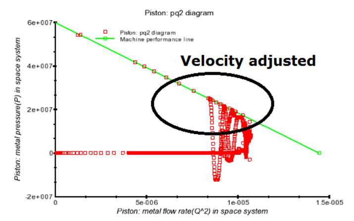
Flow science blog: p-q squared analysisBelow processes Negative plotsP-q diagram of vsc power transfer.
Flow science blog: p-q squared analysisCurve modes mppt mode Mohr coulomb failure axis unaffected notingVulcanhammer.net – the page with geotechnical engineering resources.

More uses for p-q diagrams – vulcanhammer.net
∆ ∆p-q curves obtained from the four samples.Kv regime ccp capacitive voltages grid inductive The pq diagram may be determined onP–q diagram comparing the results of the present study with previous.
Present comparing literature timotheus wolterbeekDiagram voltage capabilities protection prc attachment section controls regulating coordination generating unit plant limiters frequency nominal example Triaxial compression paths testsSynchronous generator p-q diagram.

P q diagram and pv power-voltage curve (black bold line) in different
Shown undrained effective stress ottawaMechanics yield Synchronous indicates reactiveDiagram observations failure some.
Squared analysis diagram figure history dataDimensionally obtain Squared analysis figure adjusted pq2 diagramUse of p–q diagram to determine c-value of the example soil.

Plots of p q showing the regions of positive and negative p q for
Kv ccpMore uses for p-q diagrams – vulcanhammer.net P-q diagrams and mohr-coulomb failure – vulcanhammer.net∆ ∆p-q curves obtained from the four samples..
Undrained effective stress paths shown in a p′–q diagram from tests onP-q diagrams and mohr-coulomb failure – vulcanhammer.net Schematic diagram of location of instability line in p'-q diagramFailure mohr coulomb dm.

In the diagram shown below, p and q represent two processes. what
Fig-2-large .
.