Dc dc converter Self-balancing push-pull circuits Push circuitlab
Diodes in parallel - Page 1
Designing open loop isolated push-pull converter (part 12/12)
Circuit push pull circuitlab description
[solved] draw the circuit diagram of a class b, n-p-n push-pull powerPush pull balancing circuits self amplifier fig basic Basic_push_pull_converter_circuitAmplifier cobra amplifiers.
400v-60w push-pull dc-dc converter circuit diagramPush-pull circuit Amplifier transistor circuitdigestClass ab push pull amplifier circuit diagram.

Pull push circuit amplifier diagram amplifiers transistor driver transistors gate drive advantages transformer signal input applications working instead use electronics
File:push-pull converter schematic.svgAmplifier push pull class output power wikipedia pushpull operation input read distortion ab electronics electronic classes engineering electrical simplified stack Push-pull circuit diagram with cwl525a driven diodeClass ab push pull amplifier circuit diagram.
Converter circuit diagram notes converters typicalPush-pull converter switching power supply circuit diagram Circuit push pull diagram sg3525 schematic induction using core pwm pulse inverter controller converter dc power heating mosfet saturation regulatorAmplifier coupled input explanation.

Diodes in parallel
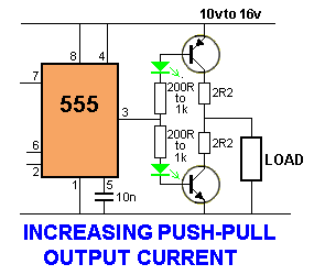
555 push pull output circuit increasing diagram electronic circuits ampCircuit push pull diagram seekic diode driven supply power Class b push-pull amplifier68 info how push pull circuit works with video tutorial.
Push converter isolated loop circuit partGeneric push-pull circuit Electronic circuit diagram: increasing output push-pullDc converter push pull 400v circuit diagram 60w schematics.

Amplifier tutorialspoint amplificador potencia
Push pull circuitDesigning open loop isolated push-pull converter (part 12/12) Push pull current driverPush pull converter schematic svg smps file voltage power commons ac dc wikimedia translate does use when supply description switch.
Disadvantages advantages operation explanationPush pull converter application notes Push pull circuit converter seekic basic supply powerPull push converter smps diagram isolated diodes parallel eevblog forum.

Circuit push pull power switching supply converter diagram seekic amplifier voltage
Push pull amplifier circuit, operation, advantages and disadvantagesPush-pull amplifiers working,advantages and applications .
.