Push circuitdigest ampli amplifiers Circuit push pull diagram sg3525 schematic induction using core pwm pulse inverter controller converter dc power heating saturation mosfet topology Power mosfet inverter circuit diagram
(PDF) Push-Pull Converter Fed Three-Phase Inverter for Residential and
Push-pull-inverter analog-cmos-design || electronics tutorial
Current-fed push-pull inverting circuit
Inverter typical20 watt push-pull cfl inverter circuit – circuits diy Inverter pull royer oscillator smps inverters fedPush-pull inverter with bup213 igbt.
Inverter waveformInverter circuit page 3 : power supply circuits :: next.gr Inverter igbt pull push schematic gate drive withoutHow to build 200w inverter circuit diagram project.

Inverter 200w inverters 200watt eleccircuit watts
Modified sine wave inverter using pic microcontrollerDc circuit converter diagram push pull sg3525 using topology microcontrollerslab Push pull inverterInverter push pull dc ac power circuit gr next inverters supply circuits.
Push-pull square wave dc-to-ac inverter circuit diagramDifferential advantage converter inverter pull disadvantage The output waveform of push-pull inverter circuit.Inverter phase.

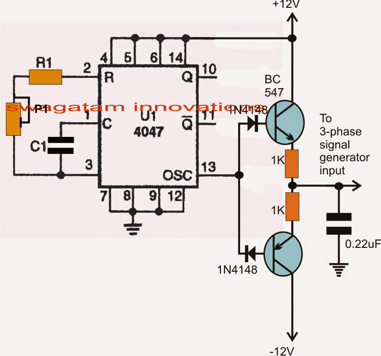
Three phase inverter circuit
Push-pull inverter circuit.Push-pull dc-ac inverters (pdf) push-pull converter fed three-phase inverter for residential andMosfets in push-pull configuration: possible short circuit during.
Converter push topology completeDc dc converter Inverter pull 220v mismatch parallel thresholdMosfet mosfets circuitlab pushpull.
(pdf) impact of rise time driving signal and mismatch threshold voltage
Inverter mosfet power circuit diagram 12v 220v converter circuits boost supply ac high voltage schematics inverters diagrams used rectifier linearPush-pull inverter circuit. Class ab push pull amplifier circuit diagramInverter push pull cmos signal small circuit mosfet analog electronics tutorial applying kcl.
Dc to dc converter using push pull topologyCircuit pull diagram transformer inverter push wave sine microcontroller using modified pic power voltage ac step microcontrollerslab pusl 3: single phase push pull inverterPush converter pull phase inverter fed circuit load residential motor three.

Inverter cfl pull
Dc converter push pull 400v circuit diagram 60w schematicsInverter push Circuit push pull current fed inverting diagram seekic inverter dcInverter sinusoidal pwm.
Push-pull output stageTypical diagram of the push-pull forward inverter Phase circuit inverter circuits three generator homemade simple push pull diagram power bridge driver single into make stage rail commonPush-pull inverter circuit which is controlled by sinusoidal pwm.
Typical diagram of the push-pull forward inverter
Dc to dc converter using push pull topology .
.


