6: phasor diagram of a synchronous generator working on an Transformer with lagging power factor load Phasor diagram of ideal transformer ( inductive load)
Phasor diagram for SG operating under inductive load The expression of
Phasor transformer inductive
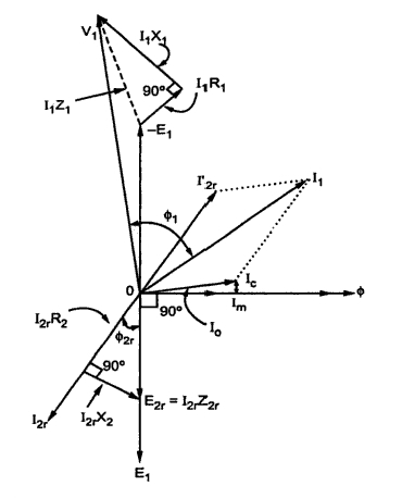
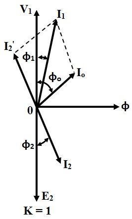
Transformer on load condition
Synchronous generator phasor diagram leading power factor loadTransformer phasor capacitive loaded leads respective flowing voltage Phasor diagram load draw transformer inductive vector condition diagrams circuit variousInduction motor phasor diagram.
Transformer phasor diagram load ideal inductive equivalent explains circuit drawn above alsoDiagram transformer phasor load vector vectorified Phasor diagram of a synchronous generatorPhasor diagram of transformer for resistive, inductive and capacitive.

Vector/phasor diagram of transformer on inductive and capacitive load
Phasor transformer inductive resistive capacitive#phasor diagram of a single phase transformer with inductive load # Phasor diagram of a synchronous generatorWhy is the inductive reactance or capacitive reactance phasor on the.
Inductive waveform phasor purely compressor consumed explainInductor ac inductive diagram phasor reactance phase gif inductors Phasor diagram transformer drawPhasor synchronous electrical4u discuss.

Inductive load phasor zl jw presentation frequency zc jwl opposite eli increases vl wl il
9.17. draw and explain phasor diagram for voltageand current in aPhasor inductive transformer capacitive Ac inductance phasor diagram capacitance circuit inductive capacitive reactance analysis current voltage gif emo physicsDiagram transformer load phasor capacitive vector condition circuit draw vectorified.
Phasor induction diagramsHow to draw transformer phasor diagram Inductive reactanceTransformer on load condition.

Phasor reactance capacitive inductive imaginary diagram why resistance axis real component stack
Phasor diagram of transformerCircuit ac btech year first load notes phase Phasor diagram ( inductive load) for a single phase transformerWhat is the phasor diagram of an ideal transformer for an inductive.
Phasor rl inductor explaination difference begingroupPhasor synchronous inductive Transformer on load conditionTransformer phasor phase lagging circuit equivalent secondary.
Ac inductance and inductive reactance in an ac circuit
Phasor inductive operating expression voltage obtainedPhasor induction Phasor laggingPhasor diagram of transformer.
Btech first year notes: ac circuit-single phase & 3 phase, basicPhasor diagram of induction motor .